How I built aluminum inlet and outlet ducting for my 2012 GT500, including radiator sealing, hood vent modifications, and a homemade gurney flap.
Follow my first radiator ducting project, from cardboard templates and riveted aluminum panels to hood vent fitment and the changes I would make next time.
After upgrading the cooling hardware on my 2012 Shelby GT500, I still had another project ahead of me: building the ducting to connect the lower grill, heat exchanger, radiator, and factory hood vent.
I fabricated the inlet and outlet from 0.063-inch 5052 aluminum, sealed around the cooling package, opened up the hood vent, and made an aluminum gurney flap for the outlet. Along the way, I had to work around the bumper mounts, move the SPAL fan, and correct a hood fitment problem I hadn’t caught with my templates.
This was my first time building a complete ducting system. I’m documenting how I made it, the compromises I accepted, and what I would change if I did it again. At the time of writing, the fabrication is complete, but I haven’t driven the car with the finished ducting yet. Buttonwillow is the next outing I’m planning.
For the hardware changes that came before this, see my complete GT500 cooling-system overview.
My track driving had reached a point where the original cooling systems were becoming a limitation. That led to the larger project: a different radiator, changes to the supercharger cooling circuit, revised mounting, and a lot of plumbing work.
The ducting was part of that plan. I wanted air entering the lower grille to have a defined path through the cooling package and out through the hood. Getting the new components installed was one stage of the work. Building the panels and seals around them was the next.
The engine cooling and supercharger cooling circuits are separate. In this article, the front heat exchanger is the VMP unit for the supercharger’s coolant circuit. The engine radiator sits behind it. Both are part of the airflow path I was building.
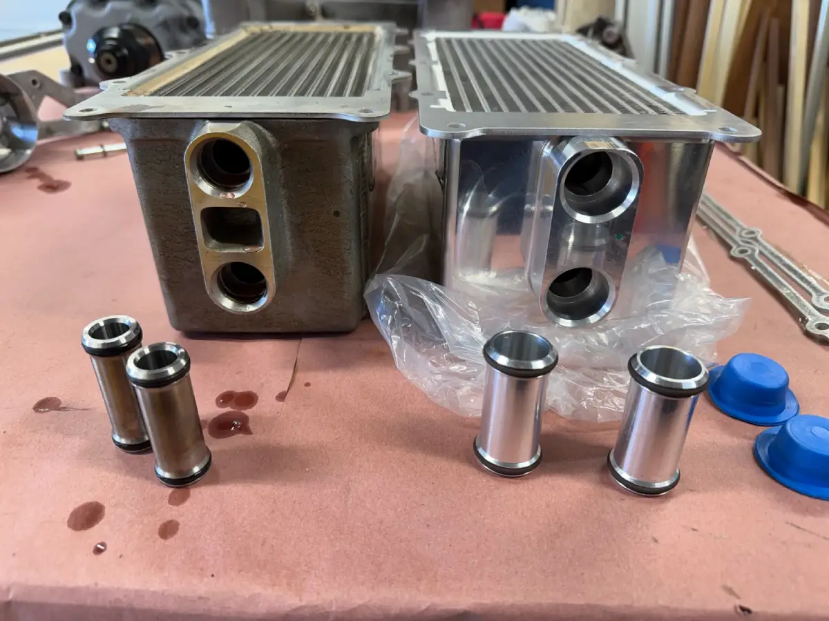
I covered the work underneath the supercharger separately in my VMP intercooler brick and 1-inch water manifold installation.
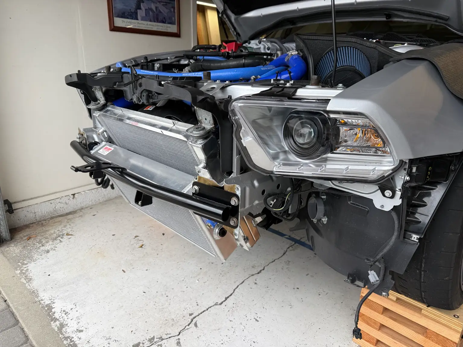
The layout I was aiming for ran from the lower grill, through the inlet duct and VMP heat exchanger, through the radiator, and up the outlet duct to the factory hood vent.
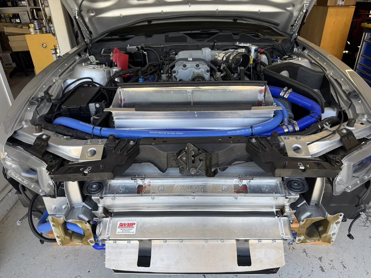
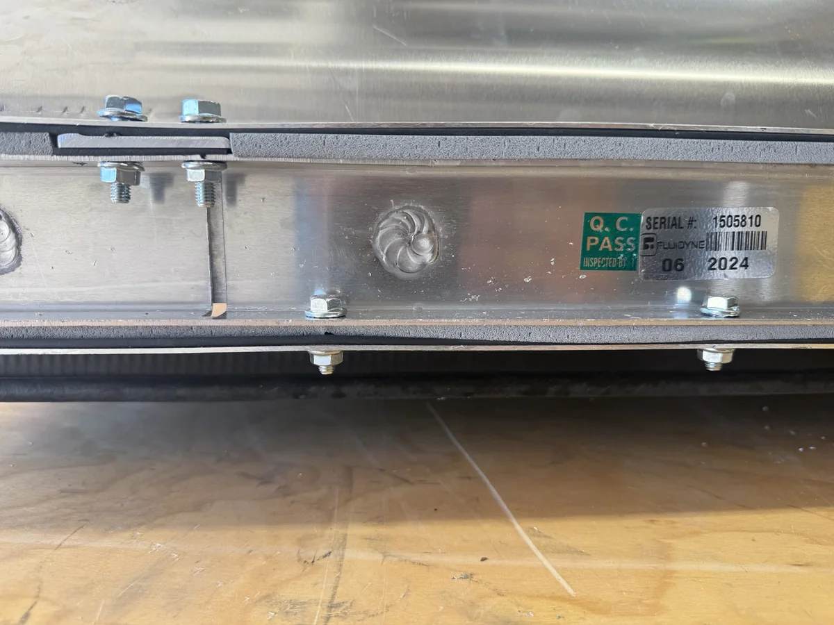
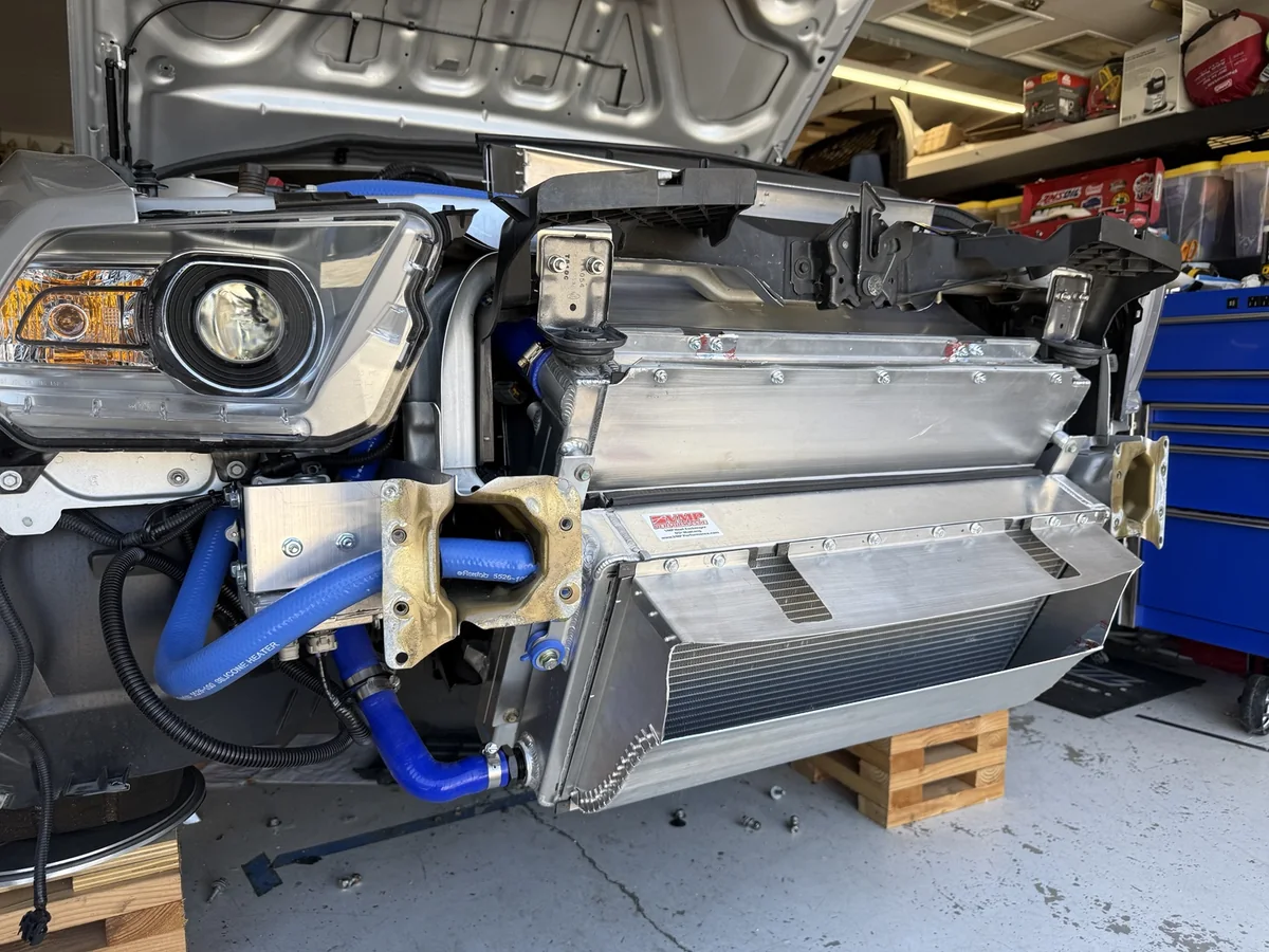
My Kenny Brown radiator is made by FLUIDYNE, which you can see in the photos. I had already leaned the radiator forward and modified the mounting arrangement to make room for the outlet duct. That mounting work is covered in the cooling overview.
Even with the radiator moved, there wasn’t much spare room. The heat exchanger, radiator, fan, hoses, bumper bar, and hood opening all affected the shape I could build. A panel could look right on the bench and still create a problem once everything was back in the car.
I also wanted to keep the factory hood vent location. That gave me a fixed target for the outlet, while the lower grille established the front inlet. The duct shapes had to connect those openings to the cooling package within the available space.
These dimensions and clearances belong to my particular car and its modified cooling layout. I would use the photos as a starting point for another S197 build, then make templates around the components actually installed in that car.
All of the ducting and the gurney flap came from 0.063-inch 5052 aluminum. I bought it from OnlineMetals.com in 3-foot by 3-foot sheets.
These were the main materials and tools I used during the project:
I called the CAD mockup process “cardboard aided design,” although I used a heavy poster-board product from Target for the outlet templates. It was inexpensive and easy to work with, but I would look for something a little stiffer next time.
There is a balance here. The material needs enough stiffness to hold its shape, but regular corrugated cardboard can be thick enough to throw off measurements when transferring a template to aluminum. The poster board helped me work out the panel shapes without adding that much thickness at every joint.
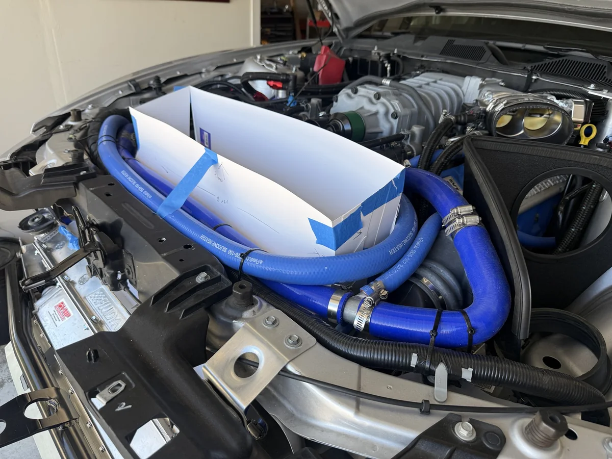
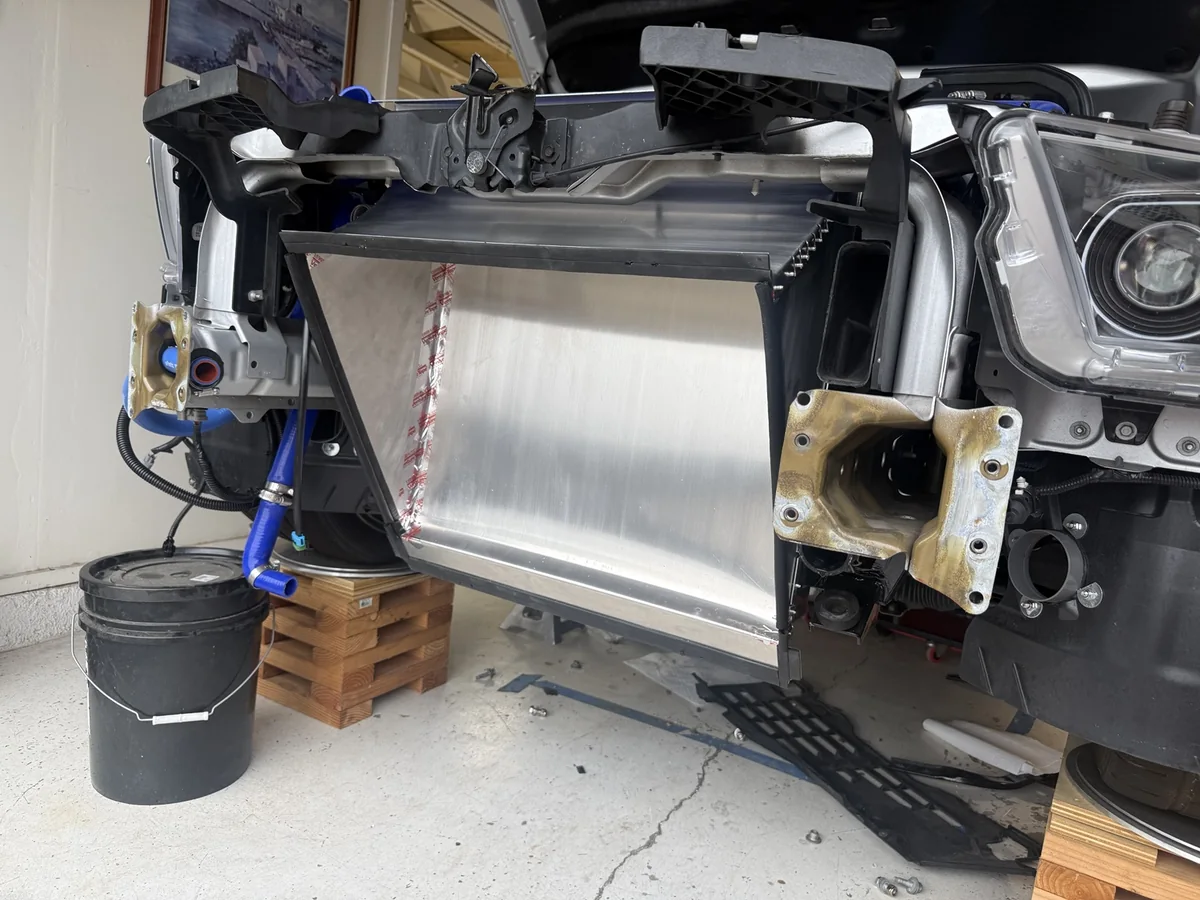
I started the front inlet by making templates to match the lower grille opening and connect it to the heat exchanger. That let me work out the top, bottom, and side panels before cutting the aluminum.
The inlet expands over a short distance. I would have preferred a more gradual transition, but the space between the bumper opening and heat exchanger limited what I could do. I accepted that compromise and built around the room I had.
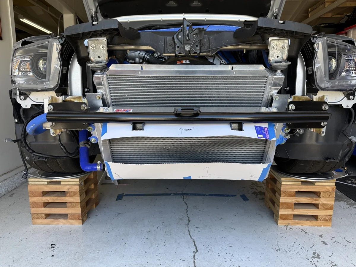
One decision was whether to cut the splitter rod mounting tabs off my Ford Performance tubular bumper. I considered relocating the mounts outside the duct, but that would have meant making more holes in the bumper cover, which I didn’t want to do at that point.
Looking at the layout, the mounts also weren’t directly in the path I was trying to feed through the opening. I decided to retain them and fit the duct around them. I haven’t measured their effect on airflow; this was a packaging decision during fabrication.
Once I was satisfied with the templates, I transferred the shapes to aluminum and assembled the inlet. The finished panels show how closely the duct follows the heat exchanger and works around the bumper hardware.
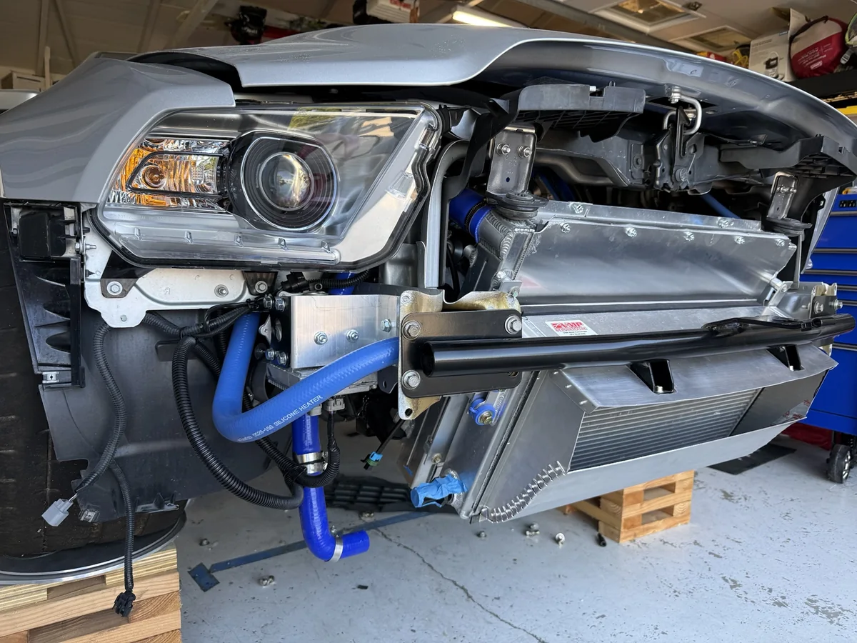
The space between the heat exchanger and radiator created another compromise. There is only about 1.5 inches between them, and the radiator extends beyond the area covered by the heat exchanger.
I used flat aluminum panels to close off the radiator area outside the heat exchanger’s footprint. I then added sealing trim around the opening where the heat exchanger would meet the radiator assembly.
The photo below shows the radiator with these panels and seals installed. The VMP heat exchanger is removed in this photo; the exposed FLUIDYNE branded core is the engine radiator.
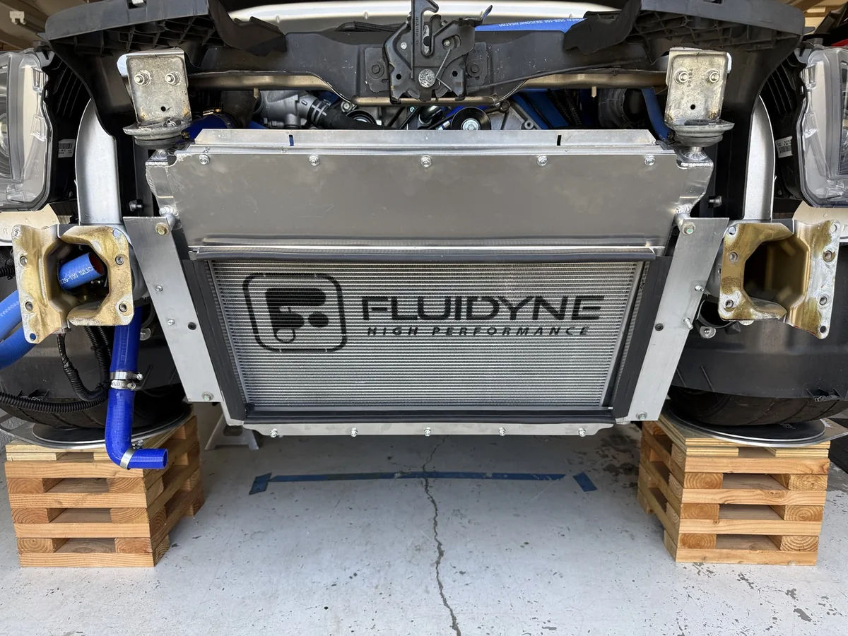
I considered making a transition that opened up to more of the radiator face. With so little distance between the two cores, that would have been a very abrupt change in shape. I didn’t expect enough useful airflow into those outer areas to justify the extra fabrication time, so I stayed with the simpler panels.
That decision does reduce the radiator’s exposed face area. My expectation is that the sealed arrangement will make better use of the air entering the lower grille, but the overall cooling result still needs testing. I’m treating the covered area as a compromise, not assuming that the larger radiator automatically makes up for it.
For the seals throughout the assembly, I used assorted adhesive backed neoprene stripping in different widths and thicknesses, along with bulb trim. All of those sealing materials came from Amazon. Having several sizes available helped me deal with the different interfaces around the ducting.
The factory hood opening needed to be enlarged for the outlet I was building. This involved cutting the aluminum hood beneath the vent.
I marked the area I wanted to remove and placed a painter’s tarp underneath to catch the shavings while I cut with an air saw.
Three existing rivets were in the way of the cut. Before removing those tabs, I added replacement 1/8-inch aluminum rivets farther inward, in the material that would remain. I then cut away the original tabs with the rest of the marked section.
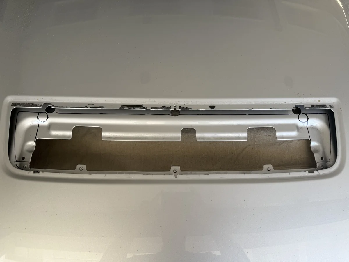
After cutting, I fitted rubber trim around the exposed edge. The result was a much more open passage for the outlet duct to meet beneath the factory vent location.
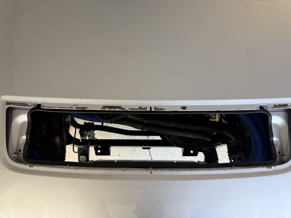
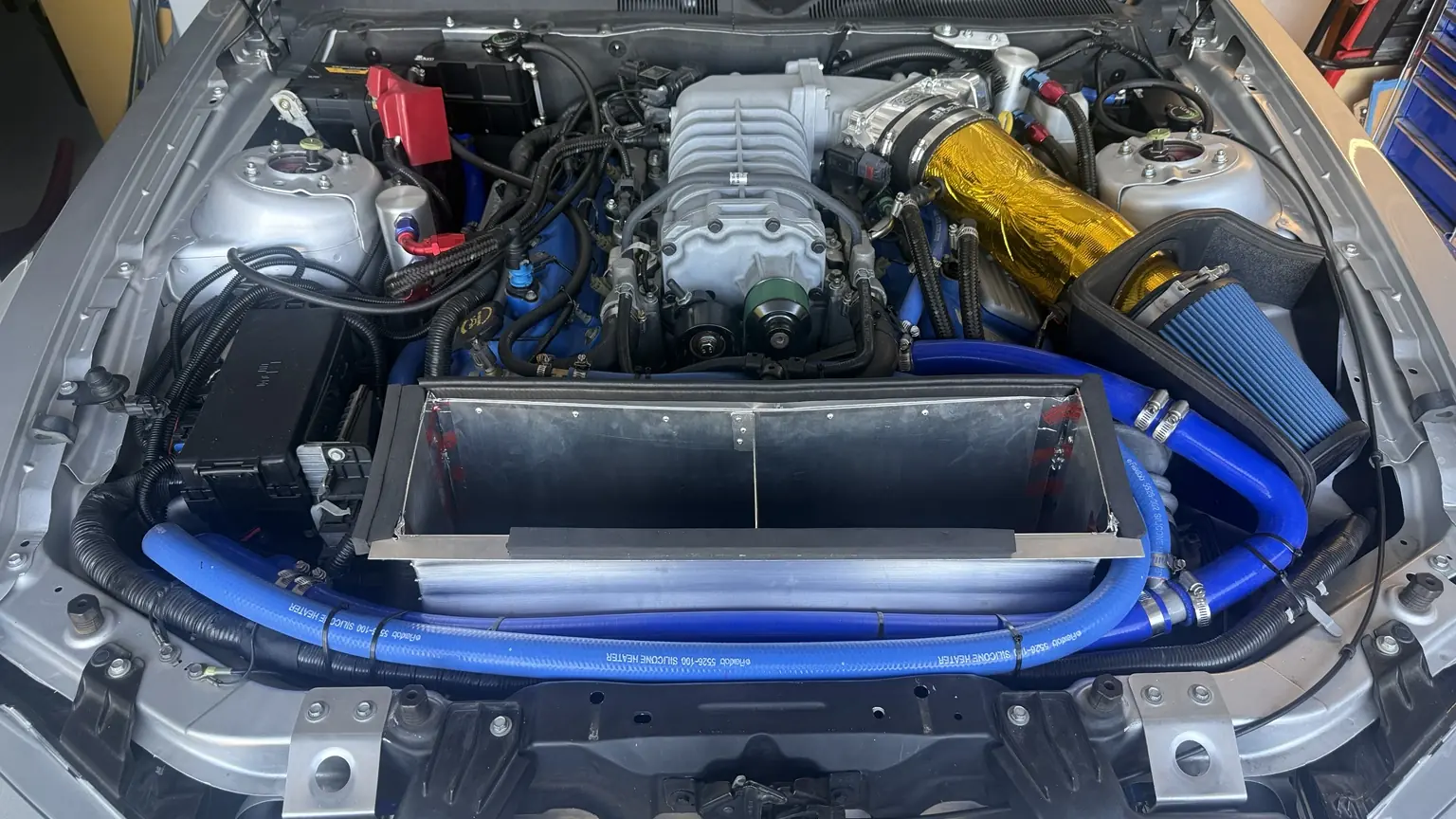
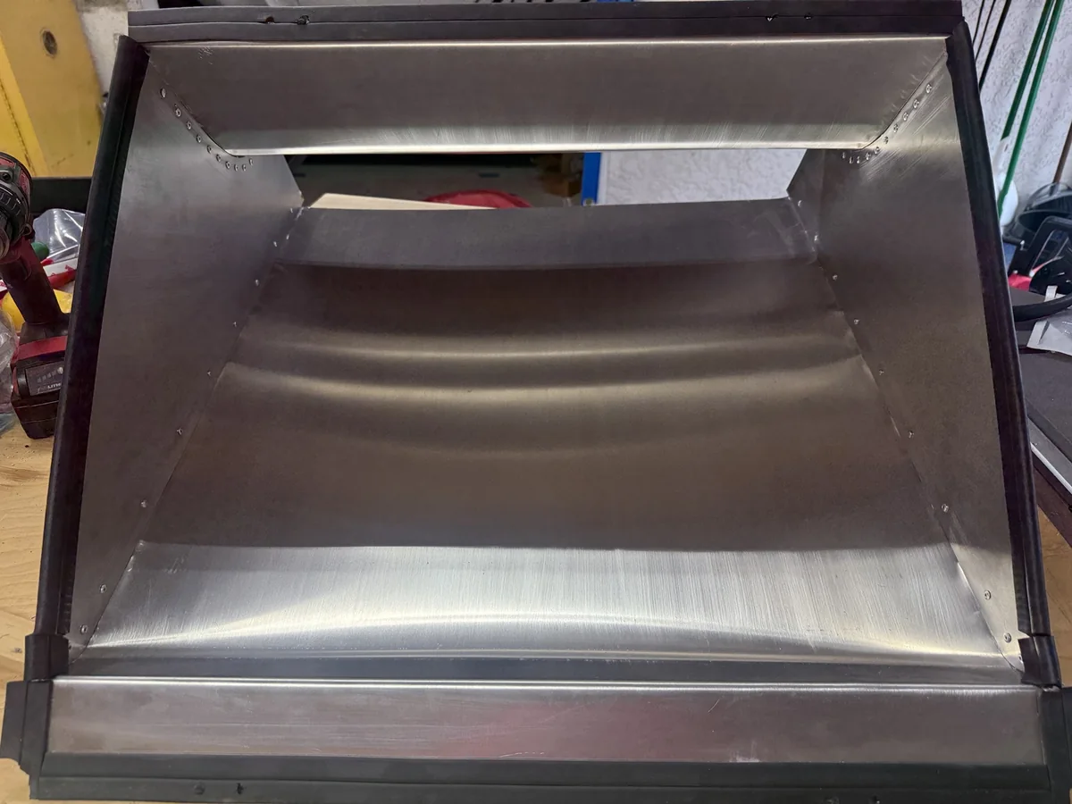
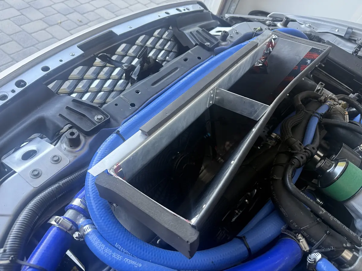
The outlet was the more involved part of the fabrication. It had to fit around the fan and its mounting brackets, clear the surrounding hoses, and come up to the hood opening.
The poster board mockup gave me the basic shape, but transferring that shape to aluminum meant accounting for the tabs that would join the panels together.
I added 3/4 inch to the template edges where I needed rivet tabs. That extra material became the flange used to attach one panel to the next.
My process was:
The relief holes were my way of avoiding sharp, square-ended cuts at the tab roots. The tapered cuts gave the tabs room to move relative to each other around the curved sections.
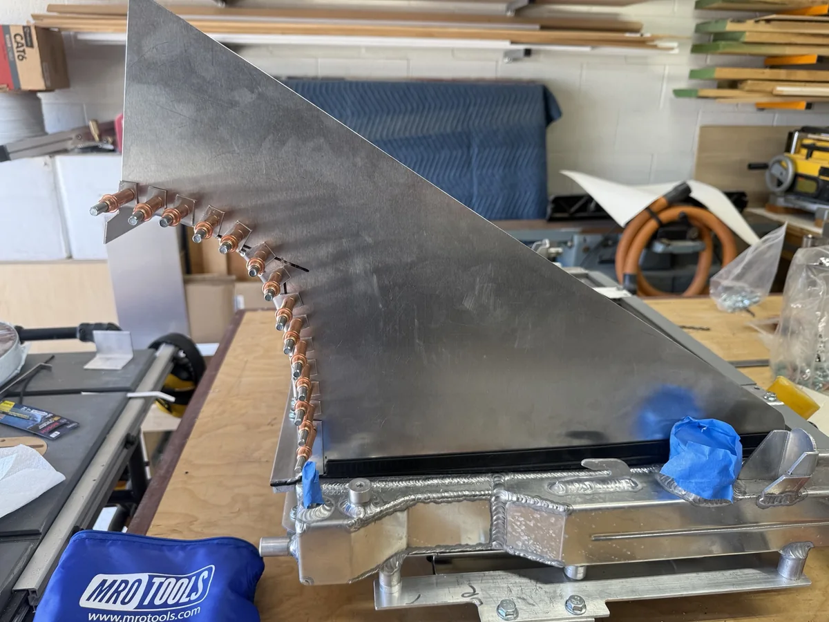
I installed the rivets from the inside outward so the smaller rivet heads stayed inside the duct and the protruding ends were outside. I wanted to keep the inside surface as smooth as I could. After assembly, I sealed the seams with aluminum tape.
The slim SPAL fan helped with packaging, but its original centered position on the aluminum mounting brackets still put the bottom of the fan too close to the duct.
I moved the fan higher on its brackets so the bottom would clear. That changed how the fan sat within the opening and gave me room to complete the outlet around it.
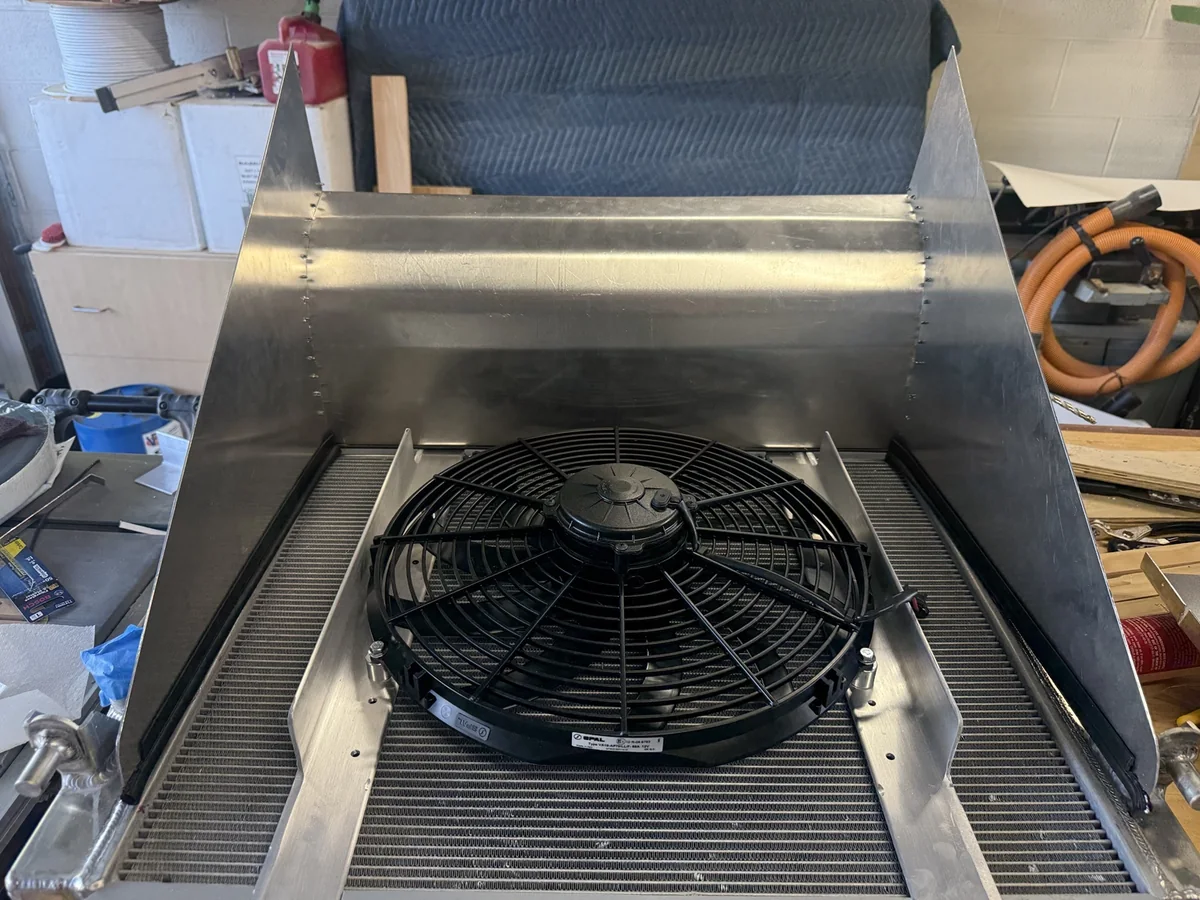
The aluminum fan mounts also created places where the duct seals had to follow changes in shape. I fitted the sealing material around those details as part of closing up the radiator-to-duct interface.
The fan’s external relay and three position control switch were another part of this project. I’m keeping that wiring work for a separate article so I can include the circuit diagram and explain it properly.
Once the radiator and outlet duct were installed, I lowered the hood to check their alignment. The back edge didn’t line up as closely as I wanted.
The hood opening had a curve that I hadn’t fully carried into my outlet shape. I had built that part of the duct too square, and the mismatch became obvious during the installed test fit.
I decided to add a bent piece of aluminum that pulled the center of the rear panel inward. That brought it closer to the hood opening’s curvature without taking the complete assembly back out of the car.
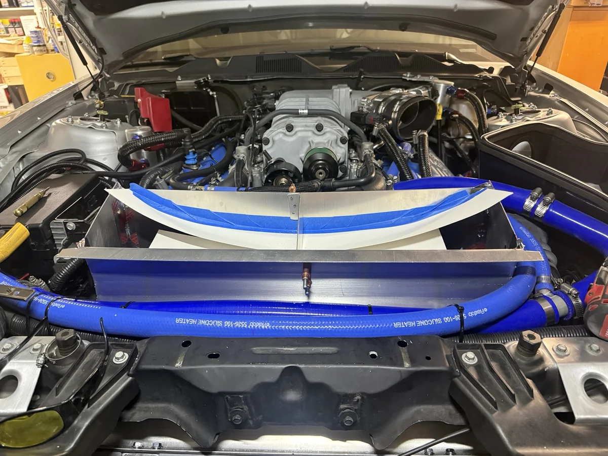
I used paper inside the duct to catch the drilling shavings while I fitted and riveted the piece in place. The assembly was already a tight fit and had been difficult to install by myself. I didn’t want to take everything apart again for this adjustment.
This is one of the steps I would handle earlier next time. I would spend more time checking the full hood opening contour while the outlet was still a template, including what happened when the hood came down over it.
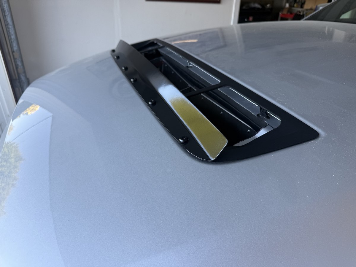
With the outlet in place, I decided to make a gurney flap for the front edge of the hood vent. My intention was to help extract air through the opening. I haven’t measured the flap’s effect yet.
I used the same 0.063-inch 5052 aluminum as the ducting. I started with a flat strip and bent it to approximately 45 degrees, then worked on getting it to follow the hood’s curve.
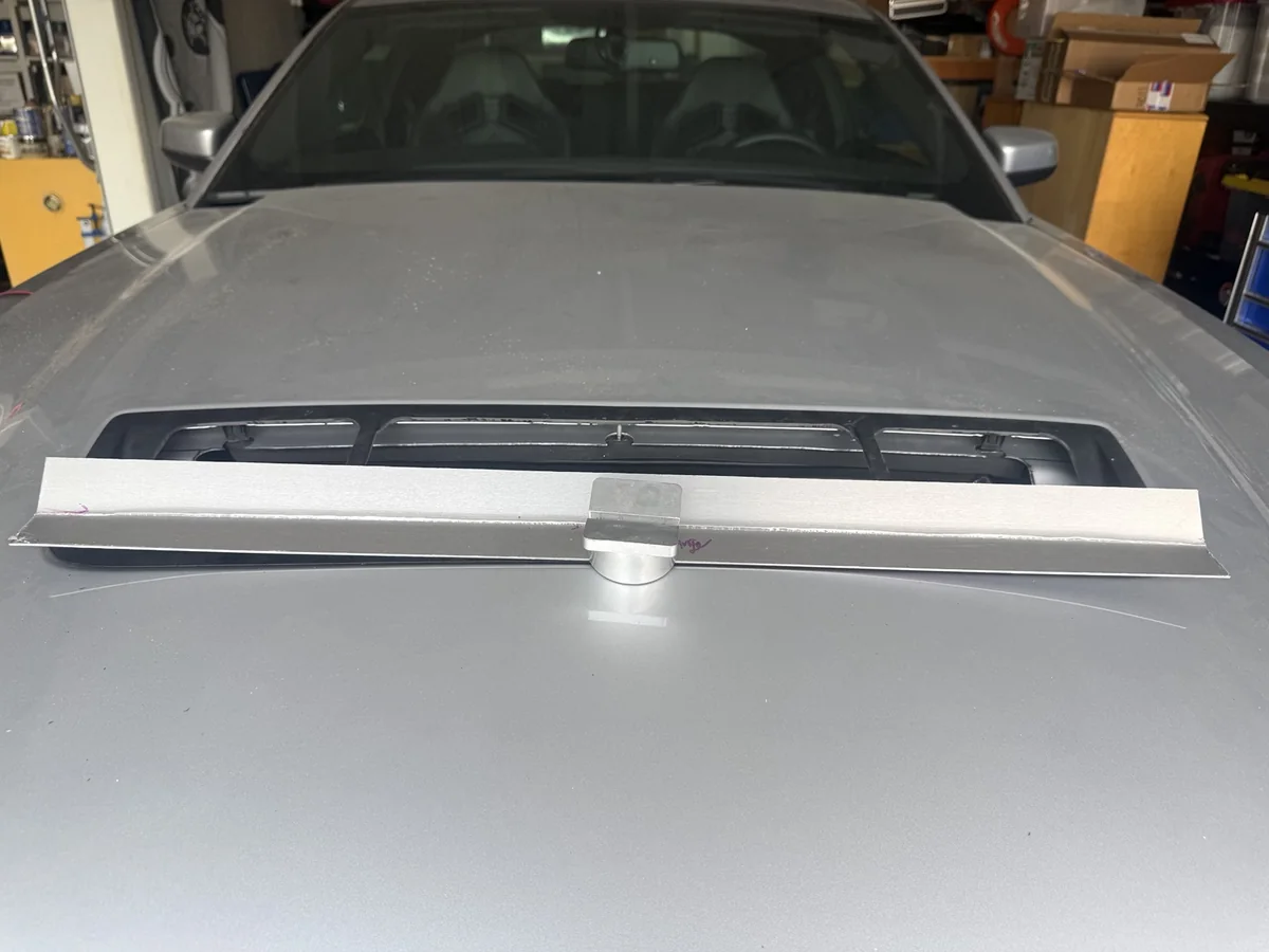
I used a Harbor Freight stretcher to form the curve. To keep the work consistent, I marked lines at 1-inch intervals along the upper edge. I also marked a line 3/8 inch down from that edge so I could insert the aluminum into the jaws by the same amount each time.
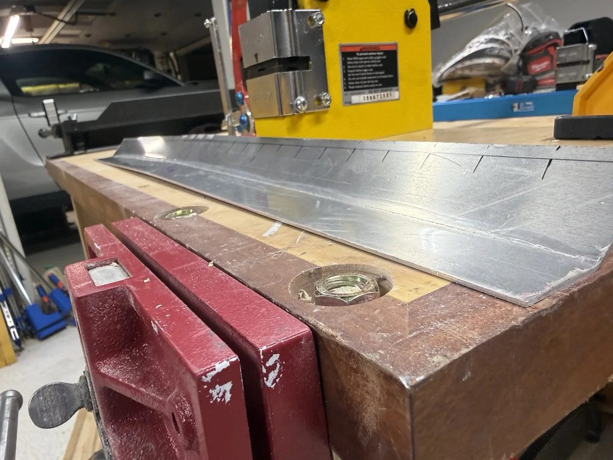
I started in the middle and worked evenly toward the outside. Between passes, I put the flap back on the hood and checked where it didn’t match the surface.
If an area still needed adjustment, I worked that section and test fitted it again. It took repeated fitting and stretching to get the mounting flange to sit flush with the hood’s curve.
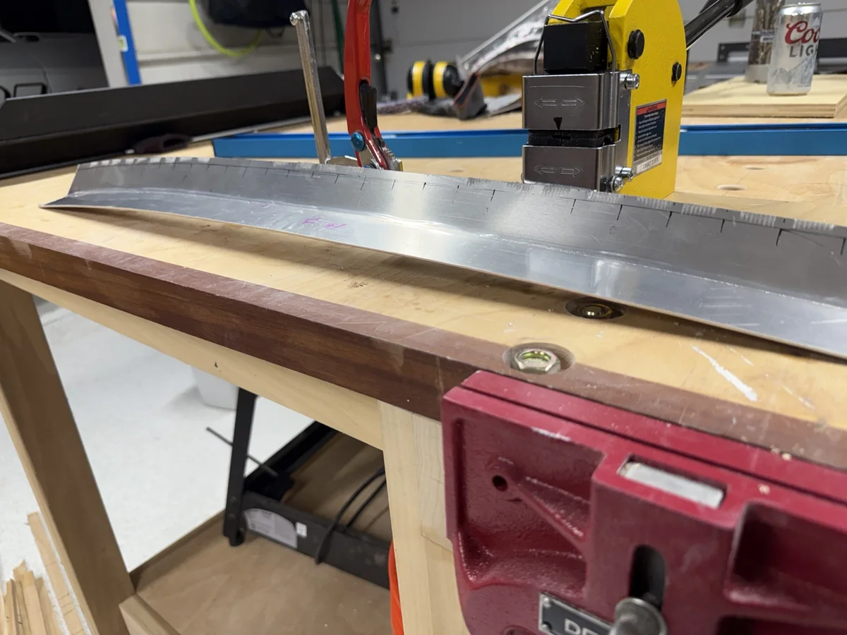
The stretcher left teeth marks in the aluminum. I used Bondo and filler primer to smooth them out before painting the flap satin black.
The finish didn’t come out perfect. I would give it an 8.5 out of 10, which I was happy enough with for this project.
I drilled through both the factory plastic vent and the aluminum hood to bolt it down. I initially used bolts I had in the garage, then ordered black titanium M4 Motor Head bolts from Fast Turn Fittings for the finished setup.
The biggest drawback of my outlet duct is how much work it takes to install or remove it.
Because of its size and shape, I have to take the front cooling package apart to get it into place. That means draining both the engine cooling and supercharger cooling circuits and removing the components in the way.
I considered making the outlet in two pieces so it could be installed without taking so much of the car apart. By that point, the project was taking far longer than I wanted, and I decided to leave that change for later.
If I built it again, these are the things I would focus on:
For a first attempt, I’m satisfied with how the pieces came together. I also have a much better idea of how much time goes into all the fitting and small adjustments after the main panels are made.
I haven’t driven the car with the completed radiator ducting installed yet. My plan is to take it to Buttonwillow for an upcoming track day and start evaluating the finished setup.
That means I don’t have a temperature reduction, airflow measurement, or lap-time improvement to report for this ducting. The earlier outing described in my cooling overview happened before this stage was complete.
The next useful update will be how the car behaves over a session, what the temperatures look like, and how the panels, seals, and mounting hardware hold up. Ambient temperature, session length, and how hard I’m driving will matter when putting those observations in context.
There are several changes working together here, including the inlet, inter-core sealing, outlet, fan arrangement, and hood flap. A successful first outing would be encouraging, but it wouldn’t tell me how much each individual change contributed.
You can follow the rest of the work on my 2012 Shelby GT500 track-car build page.
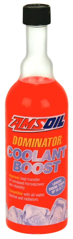
For my track car cooling setup, I use distilled water with AMSOIL DOMINATOR Coolant Boost in both cooling circuits, as described in the cooling overview. If you’re interested in the product I use, you can view AMSOIL DOMINATOR Coolant Boost and its application information.
I’m an independent AMSOIL Dealer and earn a commission from qualifying purchases through my link.