
How I rebuilt both cooling systems with a leaned radiator, VMP intercooler, EMP pump, and custom fabrication—before tackling the ducting.
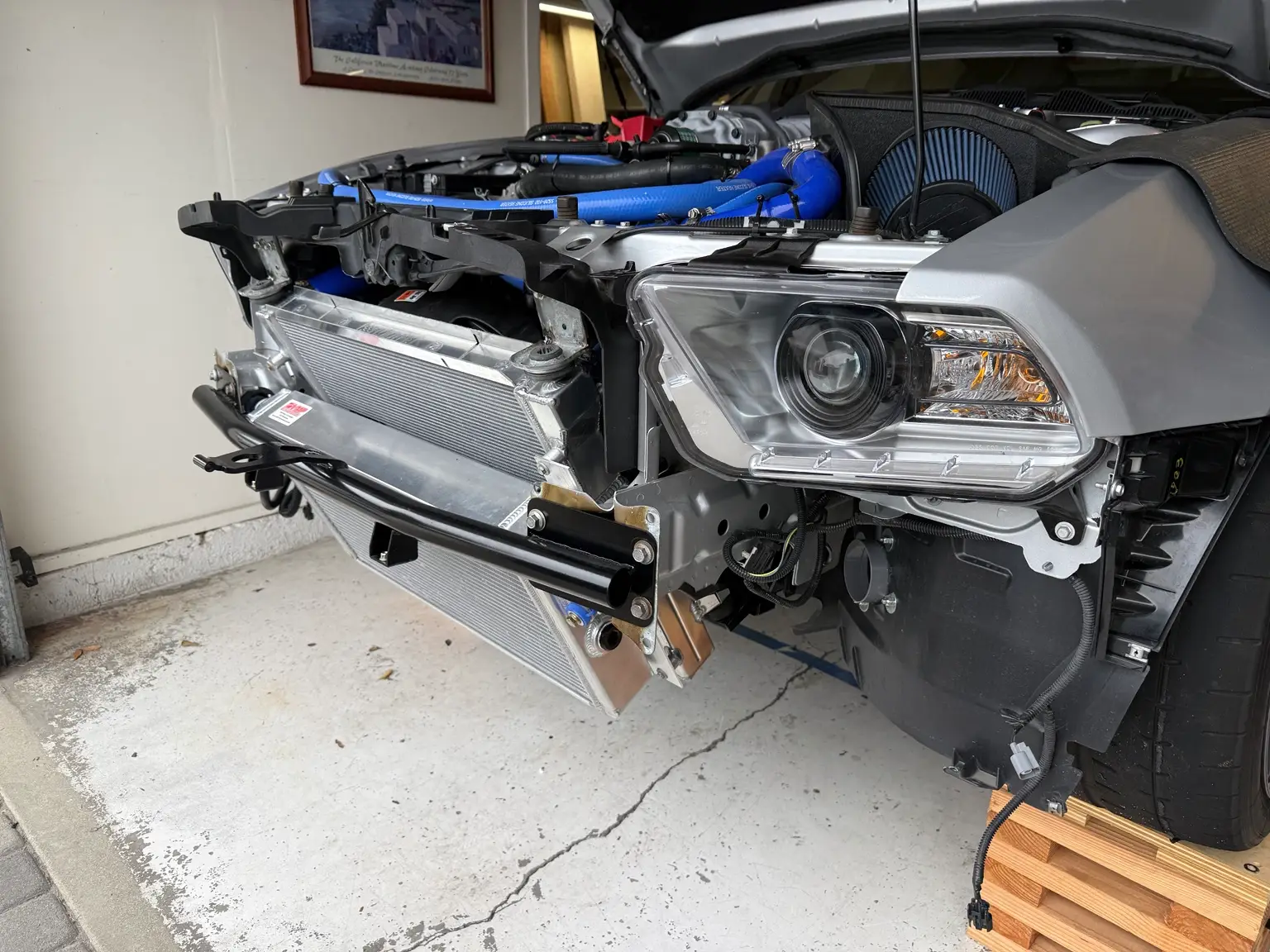
A complete overview of my GT500 track cooling rebuild, covering the radiator, intercooler, EMP pump, custom mounts, plumbing, and first shakedown.
What started as a cooling upgrade on my 2012 Shelby GT500 turned into my first major custom-fabrication project on the car.
I originally planned to install better components and get back to the track.
Instead, I ended up changing the radiator angle, fabricating mounts, rebuilding the supercharger cooling circuit, removing the A/C, and relocating the front sway bar to resolve an unexpected clearance problem.
The goal was simple: drive harder for longer without excessive temperatures cutting a session short. Getting everything to fit together was considerably less simple.
This article covers the complete first stage of the build, from the original problems to finishing the car the night before a track day. The detailed installation and fabrication work will be covered separately, followed by the next major project: fully ducting and sealing the radiator and heat exchanger.
Although this is a GT500 build, I’m also documenting the radiator-mounting and packaging work for other S197 Mustang owners considering a similar direction. These are ideas from my particular track-car configuration, not a universal bolt-on recipe.
My track driving had reached the point where the stock cooling systems were becoming the limiting factor. I was experiencing power loss and limp-mode events as engine coolant and supercharger temperatures climbed.
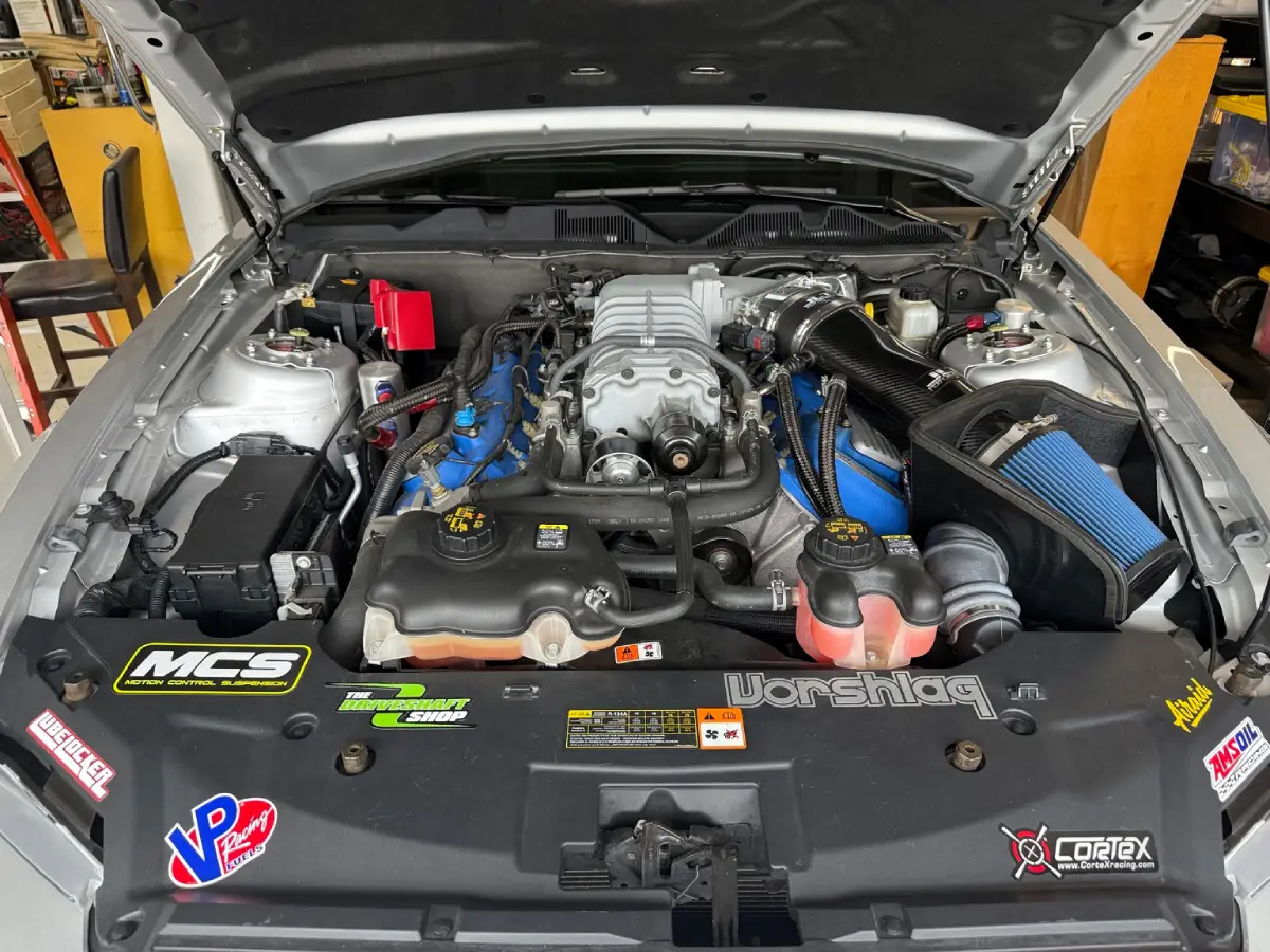
I wanted to spend more time driving and less time backing off because the car was getting too hot. This project was not about chasing a higher peak horsepower number. It was about being able to use the car’s performance for longer.
I also have a “buy once, cry once” mentality. Once I decided to address the cooling, the project quickly developed a strong “might as well” theme. Rather than replace one component and potentially take everything apart again, I decided to upgrade the major pieces together.
That decision expanded the scope substantially. By the time I finished, this was no longer just a radiator and heat-exchanger installation. It was a custom cooling package built around the way I intended to use the car.
The original plan was to replace the major cooling components, update the plumbing, and reassemble the car.
Then the VMP water manifold turned out to be on a four month backorder which I did not know when I placed the order.
That delay gave me time to research radiator positioning and cooling air ducting. I wanted to use the factory hood vent as the outlet for a future radiator duct, rather than build the system around a different hood opening. For the layout I wanted, that meant leaning the radiator forward to make room for the outlet duct.
That one decision led to several others: modifying a Kenny Brown radiator support, making upper mounting extensions, changing the front bumper reinforcement, and eventually removing the A/C.
I approached the cooling work as two connected projects:
Engine cooling: An upgraded radiator, custom mounting position, relocated Radium coolant reservoir, and revised hoses.
Supercharger cooling: A VMP intercooler brick, VMP water manifold, VMP multi pass heat exchanger, EMP pump, larger-diameter plumbing, and a separate Radium reservoir.
The coolant circuits remained separate, but fitting their components into the front of the car required planning them together.
One restriction I wanted to address was the relatively small coolant connections on the stock intercooler brick beneath the supercharger.
There are ways to modify the original intercooler, but I chose a VMP replacement with larger connections and additional cooling rows. Those features were a major part of its appeal, and the difference between the stock and replacement transfer tubes was obvious with the parts sitting next to each other. VMP’s published specifications for its replacement core describe larger inlet and outlet ports and more cooling rows than the stock core.
The flow area of a round passage increases with the square of its internal diameter. However, that does not mean total coolant flow increases by the same amount. I was trying to reduce restrictions throughout the circuit, not assume a particular flow increase from tube size alone.
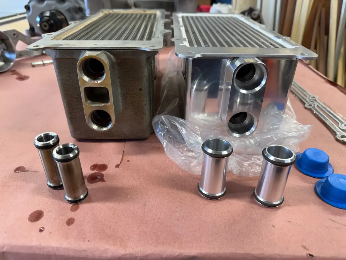
For my build, the larger core connections needed to be paired with the appropriate high-flow water manifold and transfer tubes rather than reduced back to the original connection size. I chose VMP’s one-inch-hose water manifold with its integrated auxiliary idler.
Removing the intake manifold also introduced me to a tool I had never appreciated before: long-reach hose-clamp pliers. The coolant hose at the back of the manifold was difficult enough to access that I stopped and drove to the auto-parts store to buy the proper pliers.
That was one of the smaller delays in this project, but it was memorable.
The forward radiator lean was about making room for the ducting I planned to build later. I wanted the radiator’s discharge air routed toward the factory hood vent, and the original radiator position did not give me the space I needed.
Vorshlag’s detailed S197 build threads were a major source of inspiration. Their explanations and photographs showed how they had modified the factory radiator mounting arrangement to lean the radiator forward.
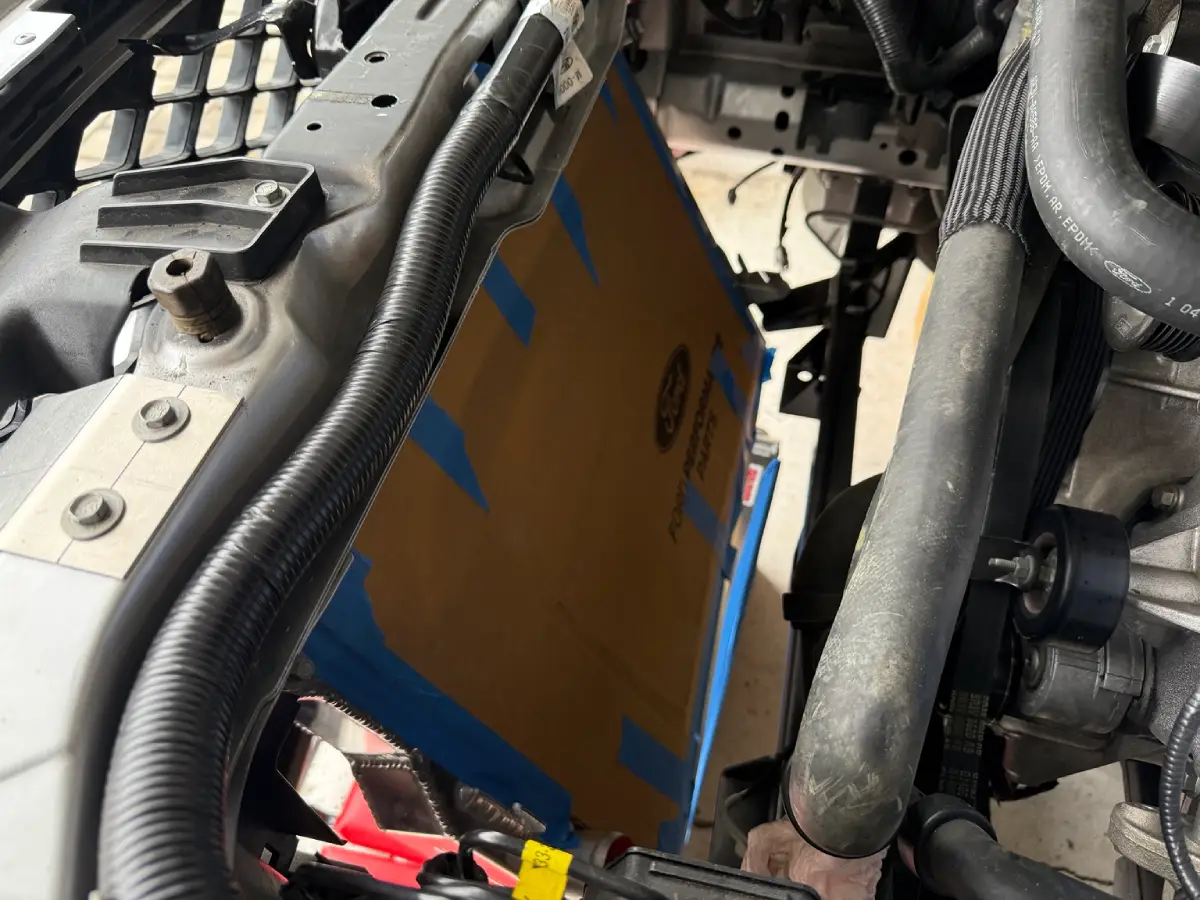
I adapted that general approach to a Kenny Brown tubular radiator support. I chose that support partly for its weight reduction and partly because its construction looked easier to modify for my application. I did not find an off-the-shelf mounting solution for the exact layout I wanted.
At the bottom, I cut off the original radiator mounting sections, shortened them, and repositioned them at the required angle before welding them back onto the support.
At the top, I used “cardboard-aided design” to work out the bracket extensions before making the aluminum versions. I also modified the factory upper radiator mounts by cutting the corners and bending the mounting section, following the approach that had inspired me in the Vorshlag thread.
The surrounding plastic bumper supports needed trimming to accommodate the extensions. The final aluminum brackets received a dimpled center hole using an inexpensive dimple die.
A huge thank you goes to Vorshlag for documenting their work so thoroughly. Their photos gave me a useful starting point, even though I still had to work out the details for my car.
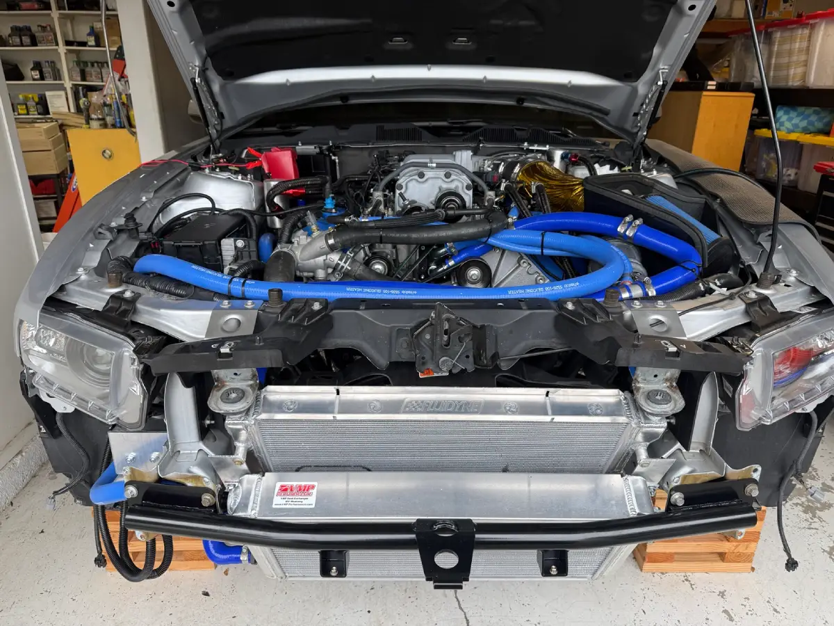
Once the radiator position changed, the heat exchanger needed its own mounting solution.
I wanted it to follow the radiator’s angle and sit where the lower grille could feed the future sealed inlet duct. In the original arrangement, a substantial part of the heat exchanger sat behind the factory bumper reinforcement. The new location was intended to give it a more direct relationship with the lower opening.
The factory bumper reinforcement also occupied space needed by the revised cooling package. I replaced it with a Ford Performance tubular front bumper bar and worked out the bumper-cover opening for the tow-hook arrangement.
Everything was tightly packaged. The radiator, heat exchanger, mounting brackets, bumper bar, and hose connections all had to fit without assuming that the original locations would still work.
I used 6061 aluminum channel, angle, and flat bar from OnlineMetals.com for the custom brackets. The heat exchanger attached to the radiator through the channel brackets and its blue mounting isolators.
At this stage, the components were positioned for the airflow arrangement I wanted. The inlet ducting, outlet ducting, and perimeter sealing were still to come.
Increasing coolant circulation was one of my priorities, so I selected an EMP intercooler pump based on its advertised high-flow capability.
Finding a location for it was another packaging problem. Between the pump’s mounting-orientation requirements and the available space, the frame area below the headlight was the practical location for my installation.
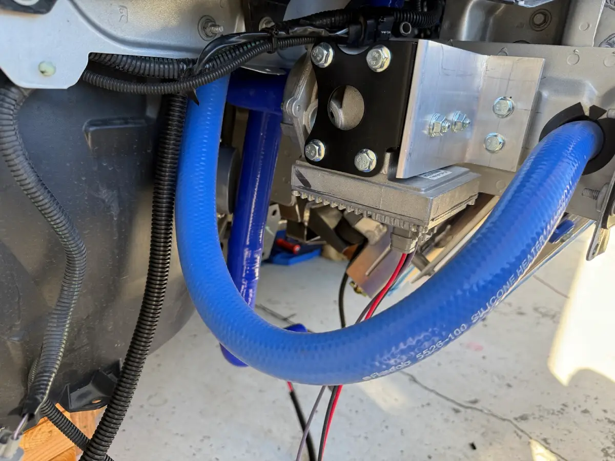
I fabricated a bracket from quarter-inch-thick aluminum angle and bolted it to the pump’s black mounting bracket. This let me attach the assembly to the frame in the position I needed.
Most of the intercooler plumbing uses 1.25-inch hose, with one section reduced to one inch because of space constraints. I sourced the hose, tubing, and silicone adapters from Pegasus Auto Racing Supplies.
The heat exchanger’s upper fitting lined up with the frame. To route the hose through that area, I made a pass-through with a hole saw and added edge protection around the opening. That was part of this specific custom installation, not a modification I would present as necessary for every S197 cooling upgrade.
I also arranged the intercooler circuit around a reservoir bypass layout inspired by the 2013–2014 GT500 configuration. The reservoir remained connected, but the main circulating flow did not have to travel directly through the tank.
The intercooler reservoir was positioned near the brake-fluid reservoir, separate from the engine-cooling tank. Making room also involved relocating a catch can to a small aluminum firewall bracket between the throttle body and brake reservoir.
With the radiator repositioned, I started looking at the factory fan assembly differently. The solid portions of its shroud looked like potential restrictions to airflow at track speed.
Ford Performance’s Dark Horse R fan-shroud bulletin provided the inspiration for opening up the shroud. The bulletin describes removing specific lower flaps and making designated openings, while preserving the structural ribs and fan supports. Its instructions limit how much material can be removed.
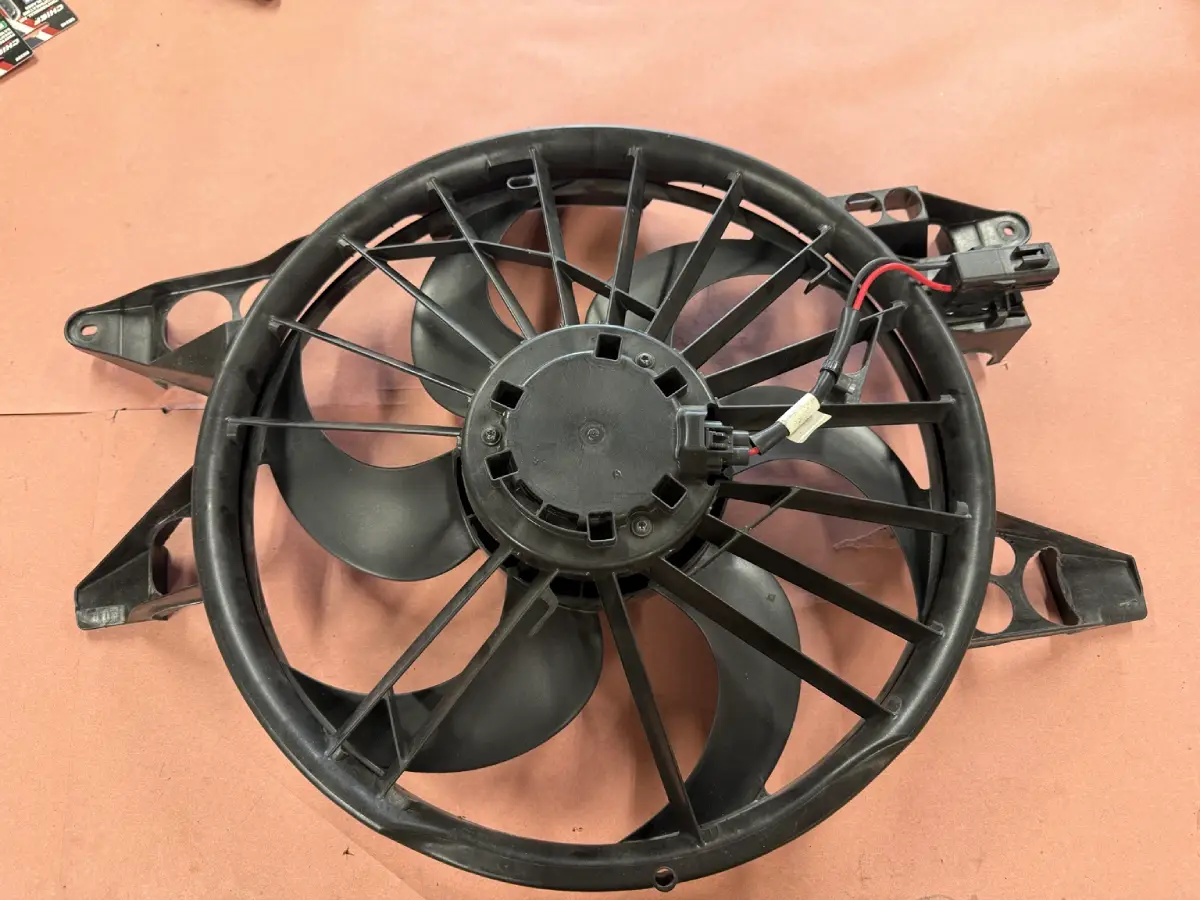
I went considerably further with my GT500 shroud, removing much more of the surrounding material and leaving a skeletonized assembly. That was my own modification, not the procedure approved in Ford’s bulletin.
The modified factory fan is the assembly I used for the first track day after this stage of the build.
It was not the final fan solution. Once I began building the outlet ducting, the stock fan still projected too far into the space I needed. That was when I changed to a slim SPAL fan.
The fan change therefore belongs to the next stage of the story: the stock assembly got the car through this initial cooling rebuild, and the SPAL came later with the ducting.
The revised radiator and heat-exchanger package was already running out of room, and keeping the A/C condenser in the stack was no longer compatible with the layout I wanted.
Removing the A/C was also a decision about the future of the car. I had not been driving it on the street much for a long time, but taking the system out meant accepting that this was becoming a dedicated track car.
I chose the BPS A/C-delete arrangement because it was the option I liked best for my build. I liked their products and was comfortable using their solution as part of the project.
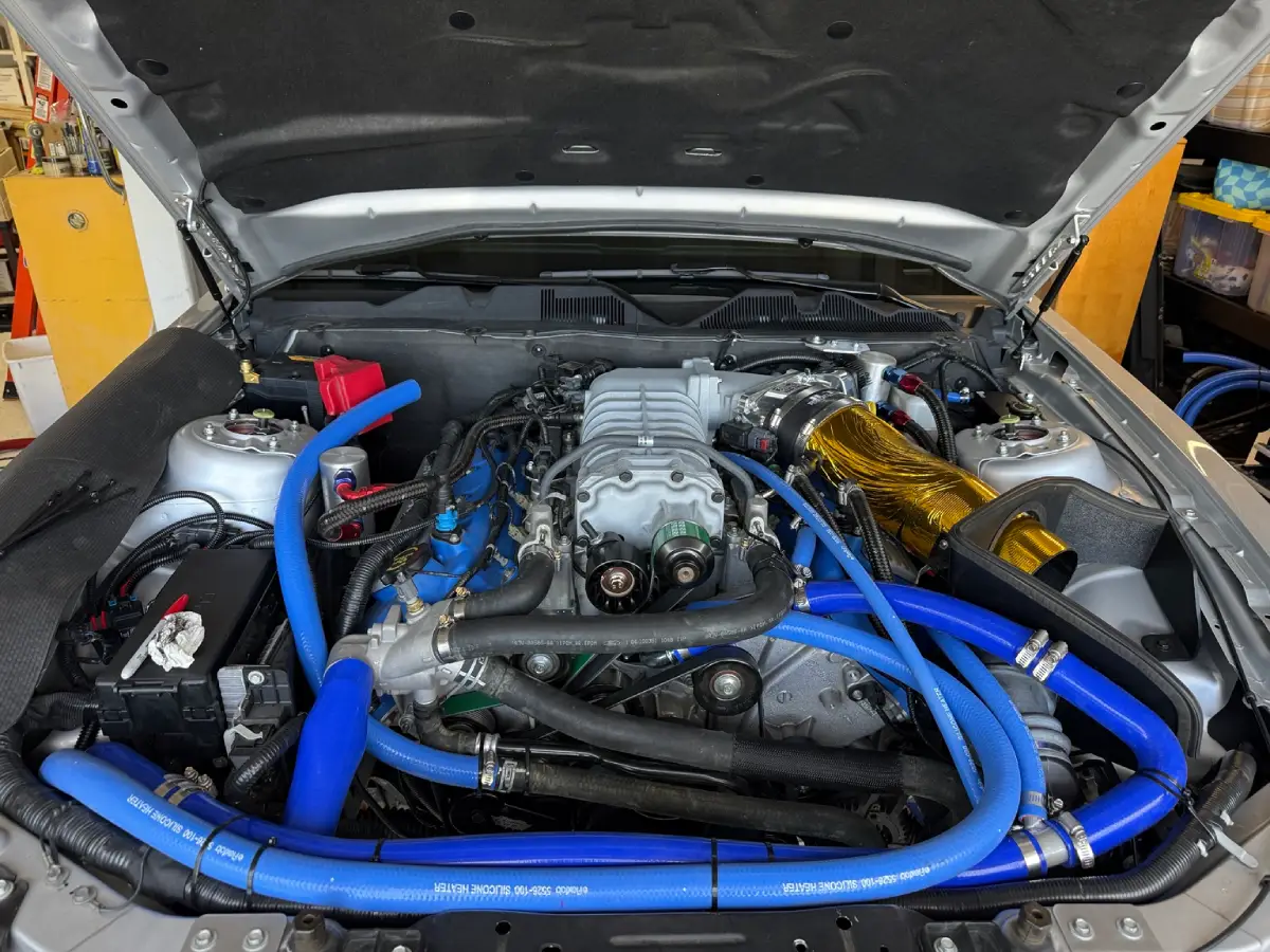
The belt was another detail that stopped being straightforward once the configuration changed. Between the A/C delete and the new water-manifold/idler arrangement, I needed a shorter belt that suited my particular routing.
I worked through available belt sizes and eventually found a suitable catalog size through a tractor-parts supplier. It was not a custom manufactured belt, just a less obvious place to find the length I needed.
That became a recurring theme: the right part existed, but finding it was no longer as simple as searching by the car’s year and model.
I thought I was getting close to final assembly when I discovered that the sway bar was contacting the oil cooler hose.
There was an important additional change behind that problem. While waiting for the backordered VMP parts, I had installed Steeda adjustable engine mounts and lowered the engine a full three quarters of an inch. I had also lowered the transmission to suit the installation.
Those changes affected the clearances around the engine, including the relationship between the oil-cooler hose and the sway bar.
After mocking up a new position, I determined that dropping the sway-bar mounts by one inch would provide the clearance I needed on my car.
Unfortunately, making that change meant taking parts back off again. I removed the Kenny Brown support, fabricated new steel mounting plates, and welded them into place before reinstalling everything.
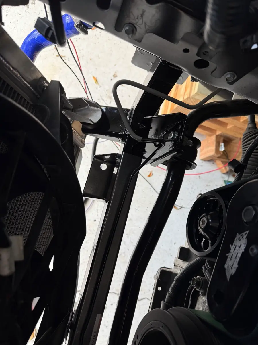
This was one of the clearest examples of how the project had moved beyond installing individual parts. The radiator position, engine height, hose routing, and sway bar mounting all affected one another.
A modification that looked finished on the workbench still had to work with everything around it once installed.
I filled both the engine-cooling and intercooler circuits with distilled water and AMSOIL Dominator Coolant Boost. AMSOIL lists the additive for straight water racing applications as well as antifreeze mixtures and describes its role in heat transfer and corrosion protection.
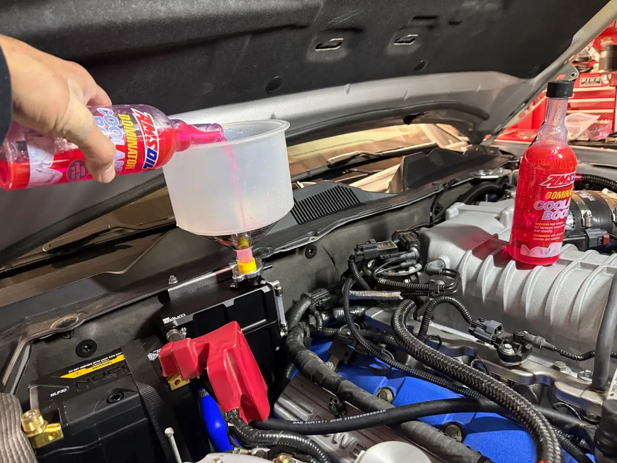
This was my track car fill choice, not a blanket recommendation to replace a street car’s specified coolant. A water based track fill should not be treated as a substitute for an appropriate freeze protected mixture.
The engine-cooling system was relatively straightforward. I used a vacuum-fill kit purchased from the MATCO tool truck, and it worked very well with the newly mounted firewall reservoir.
The intercooler circuit was much less cooperative.
Its reservoir was lower than the engine cooling tank, and I had considerable trouble getting the system filled, burped, and circulating properly. The warnings about not running the EMP pump dry made the process especially stressful. I was trying to establish circulation without damaging a brand new pump.
That experience made filling and bleeding feel like another part of the build, rather than a quick task after the fabrication was finished.
Disclosure: I’m an independent AMSOIL Dealer, and Dominator Coolant Boost is the additive I used in my own car for this project.
I had a track day booked for Sunday and took two days off work to finish the final assembly.
Earlier in the project, I had imagined completing the cooling upgrades and all the ducting before that event. By the time the hardware was installed, that was clearly not realistic. I had not even started fabricating the ducts, and that work was going to be a substantial project of its own.
The priority became finishing this stage, getting both cooling circuits filled, and reassembling the car.
The deadline also explains some gaps in the photographs. I do not have detailed installation pictures of the Radium reservoir brackets because, at that point, I was concentrating on getting the car finished rather than documenting every step.
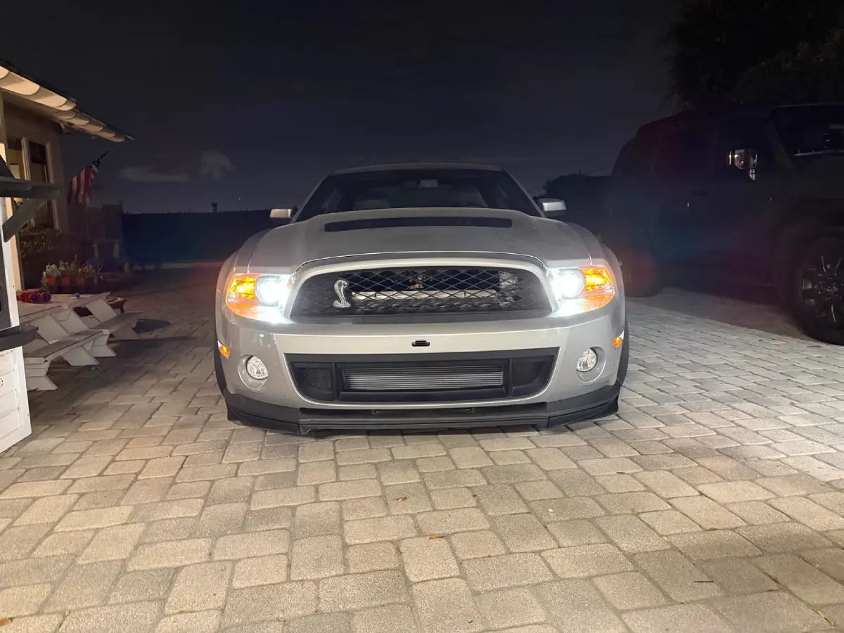
The nighttime driveway photos show the end of that push: the car back together, sitting outside the garage, the night before heading to the track.
There was still more work planned, but the custom cooling hardware was finally installed.
I do the work on my cars myself, and I normally rely heavily on Google, YouTube, and other people’s build threads to understand a job before starting it.
This project was different.
It was the first time I had taken on this much custom, one-off work without a complete step-by-step guide for my exact configuration. I could borrow useful ideas, but I still had to establish the dimensions, resolve the interference, fabricate the parts, and decide how everything would fit together.
I feel like it took about ten times longer than I originally expected.
The first track day was intentionally cautious. I had changed enough things that I did not want to immediately drive at my previous limit. The car ran great, and cooling was not an issue during that outing.
That was an encouraging shakedown, not a controlled before-and-after cooling test. I had not pushed the car as hard, and I had changed too many components together to assign a specific improvement to any one part.
The next stage was to finish the airflow side of the project: a sealed lower grill inlet, sealing around the heat exchanger and radiator, and an outlet duct leading to the factory hood vent. Building that ducting also led to the later slim SPAL fan installation.
This stage got the hardware into the car. The next stage would connect those components to the airflow path I had been planning since the backorder gave me time to rethink the entire project.

