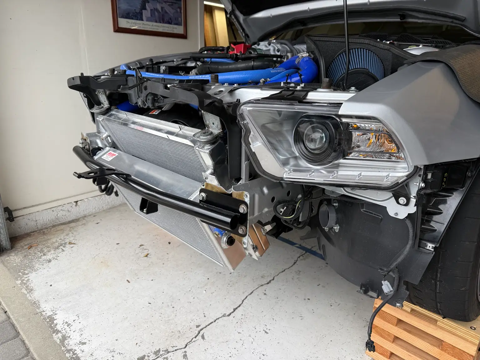
My installation of the VMP intercooler brick, matching transfer tubes, and 1-inch water manifold, including access problems and lessons learned.
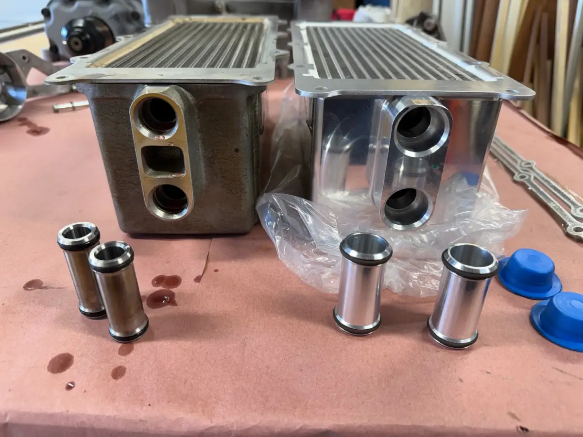
Inside my GT500 intercooler upgrade: stock-versus-VMP comparison photos, matching transfer tubes, rear hose-clamp access, and installation details.
My 2012 Shelby GT500 intercooler upgrade was part of a larger effort to make the car’s cooling systems support the way I was driving it on track. I installed a VMP intercooler brick, matching 1-inch transfer tubes, and a VMP water manifold with a built in idler pulley.
The swap was easy enough, but a few details deserve attention before starting: the rear coolant hose clamp, limited access around the intercooler mounting bolts, and the internal shape of the manifold’s hose connections. This article covers the parts I used, the problems I encountered, and what I would plan for if I did the job again.
For the rest of the project, see my complete GT500 cooling-system overview.
I had reached a point in my track driving where the stock cooling systems were no longer enough for what I was asking of the car. I decided to upgrade the intercooler as part of the complete cooling project so the core, pump, heat exchanger, and plumbing would work together.
Before choosing parts, I spent a lot of time researching intercooler coolant flow and restrictions in the stock system. Department of Boost’s intercooler system information was a useful resource, particularly its discussion of hose size, intercooler ports, and flow with different pumps. That research helped me think through the entire coolant path when selecting components.
The factory intercooler’s small transfer tubes were one of the restrictions I wanted to address. These tubes connect the intercooler brick to the water manifold. The VMP upgrade allowed me to use matching 1-inch transfer tubes as part of the larger plumbing arrangement I was building.
My goal was to give the intercooler circuit more flow capacity and support sustained track use. The brick and transfer tubes were one part of that plan; the rest of the cooling system needed attention as well.
These are the main parts I used for this portion of the build:
The transfer tubes need to match the combination of intercooler and water manifold. VMP specifies the straight 1-inch VMP-SUC027 tubes for its upgraded intercooler paired with this VMP water manifold.
For clarity, VMP-SUG000 is the Boost-Lok supercharger-to-intake gasket. It is separate from the intake manifold gaskets that seal the manifold to the cylinder heads.
Most of the work used ordinary hand tools. The tools worth having ready are a quality inch-lb torque wrench, the OEM TOOLS hose clamp plier, and a metric crowfoot wrench for the intercooler mounting bolts. My factory service manual was also an essential reference throughout the job.
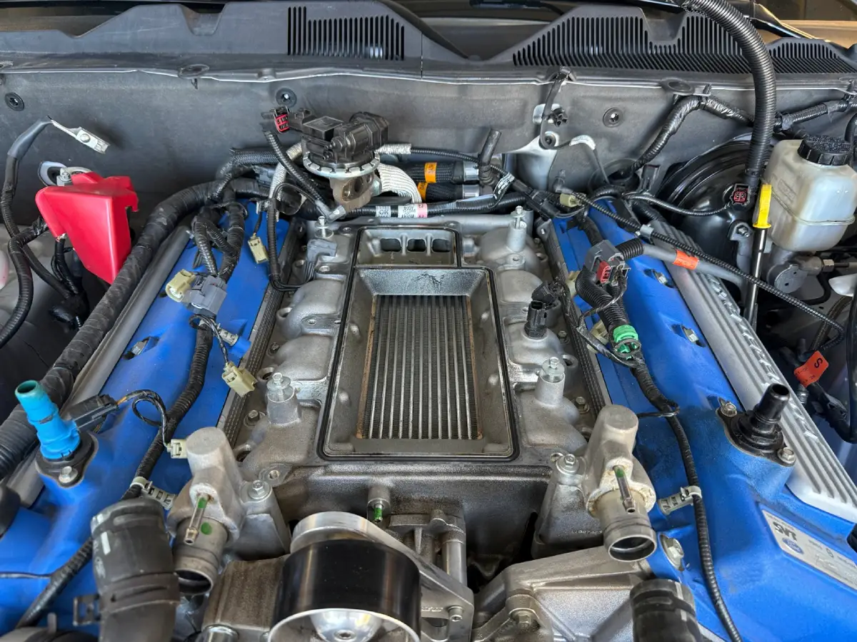
Removing the supercharger and intake manifold was straightforward overall. I used my factory service manual to guide the work and reference the torque specifications during reassembly. It is something I use regularly when working on this car.
I purchased my manual through Factory-Manuals.com, and based on my experience, I recommend having the correct service information available before starting. Being able to look up the procedure and specifications as you work makes the job much easier to approach methodically.
The main obstacle during removal was the coolant hose at the back of the intake manifold.
With the hose clamp clamp pliers i had, I could not get the rear hose clamp released. There was not enough physical space between the manifold and firewall for standard hose clamp pliers, and this stopped progress on an otherwise straightforward removal.
I made a trip to O’Reilly Auto Parts and bought an OEMTOOLS Hose Clamp Plier, part 25242. With that tool, removing the hose was easy.
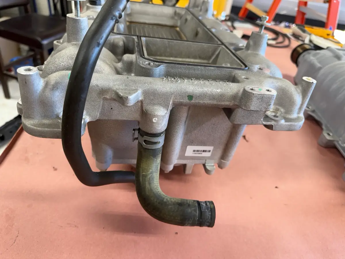
That is one tool I would have on hand before starting this job again. The right plier made a much bigger difference here than trying to work around the access problem with the tools already in my box.
With both intercooler bricks out on the bench, the differences were easier to see. The VMP core has an additional cooling row and larger coolant inlet and outlet connections.
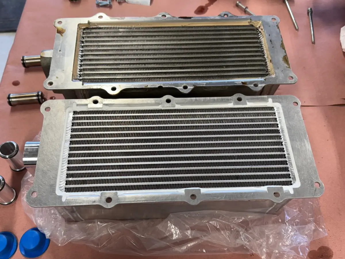
VMP lists the following specifications for the SUC050 compared with the factory core:
Factory Core
VMP Core
For my build, the larger coolant connections were a major reason to choose this core. They allowed the matching larger transfer tubes to be used with the upgraded water manifold.
The additional row and larger connections explain the hardware changes. Actual coolant flow and temperature control still depend on the assembled system, including its pump, plumbing, heat exchanger, and remaining restrictions.
I used my service manual as the torque reference during the installation. The main problem I encountered was getting a socket to fit on the supplied intercooler mounting bolts.
The bolt heads sat so close to the intercooler that I could not fit a normal socket around them. I also tried a thinner-wall Snap-on socket, and it still would not fit. On my installation, using a less bulky socket did not solve the clearance problem.
A crowfoot wrench (yes, they are ICON...) gave me access to tighten the bolts while keeping the supplied hardware.
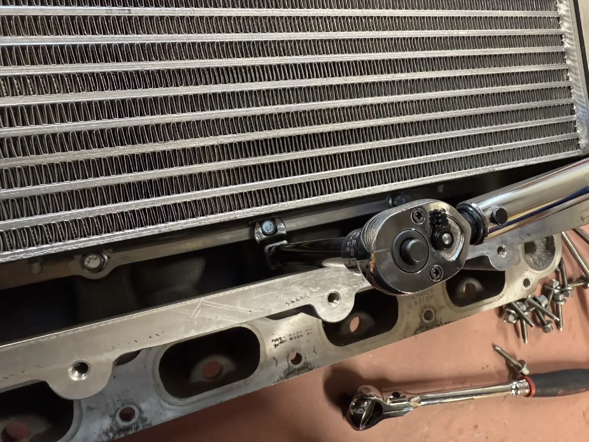
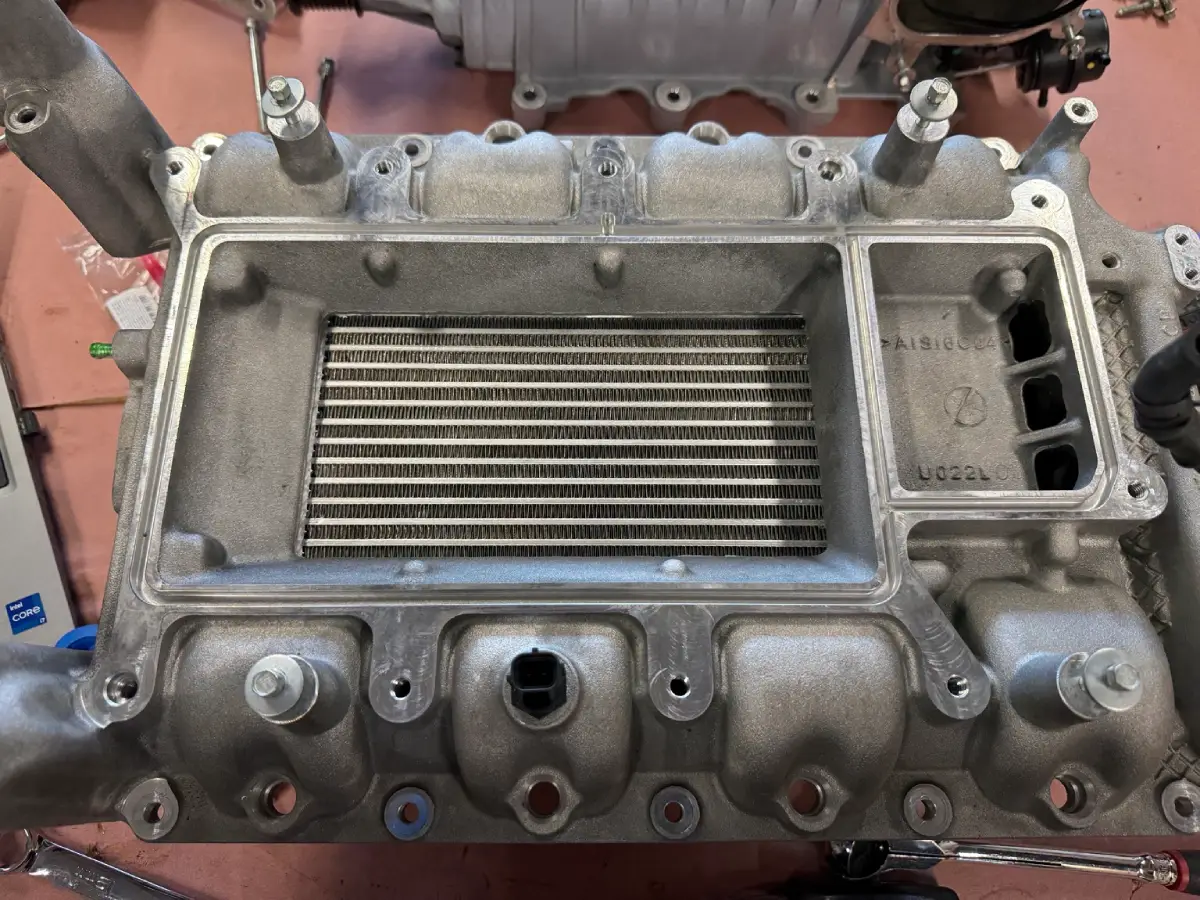
A crowfoot can be used with a torque wrench, but its orientation matters. With the line between the square-drive center and fastener center held at 90 degrees to the torque wrench handle, the attachment does not add effective length along the handle. In that arrangement, no torque-setting correction is needed.
If the crowfoot must sit at another angle, calculate the proper torque setting. TEKTON’s crowfoot torque guide explains the geometry and provides a correction calculator.
I would have preferred socket-head cap screws in this location. Driving the fastener through its center would address the need to fit a socket around the outside of the head. In my opinion, the kit’s hardware selection should make that access easier.
The practical lesson is to check tool clearance around the mounting bolts before committing to final assembly.
Installing the VMP water manifold with its integrated auxiliary idler was straightforward. I lubricated the floating transfer tubes with coolant before installation, fitted the manifold, and torqued the mounting hardware to spec.
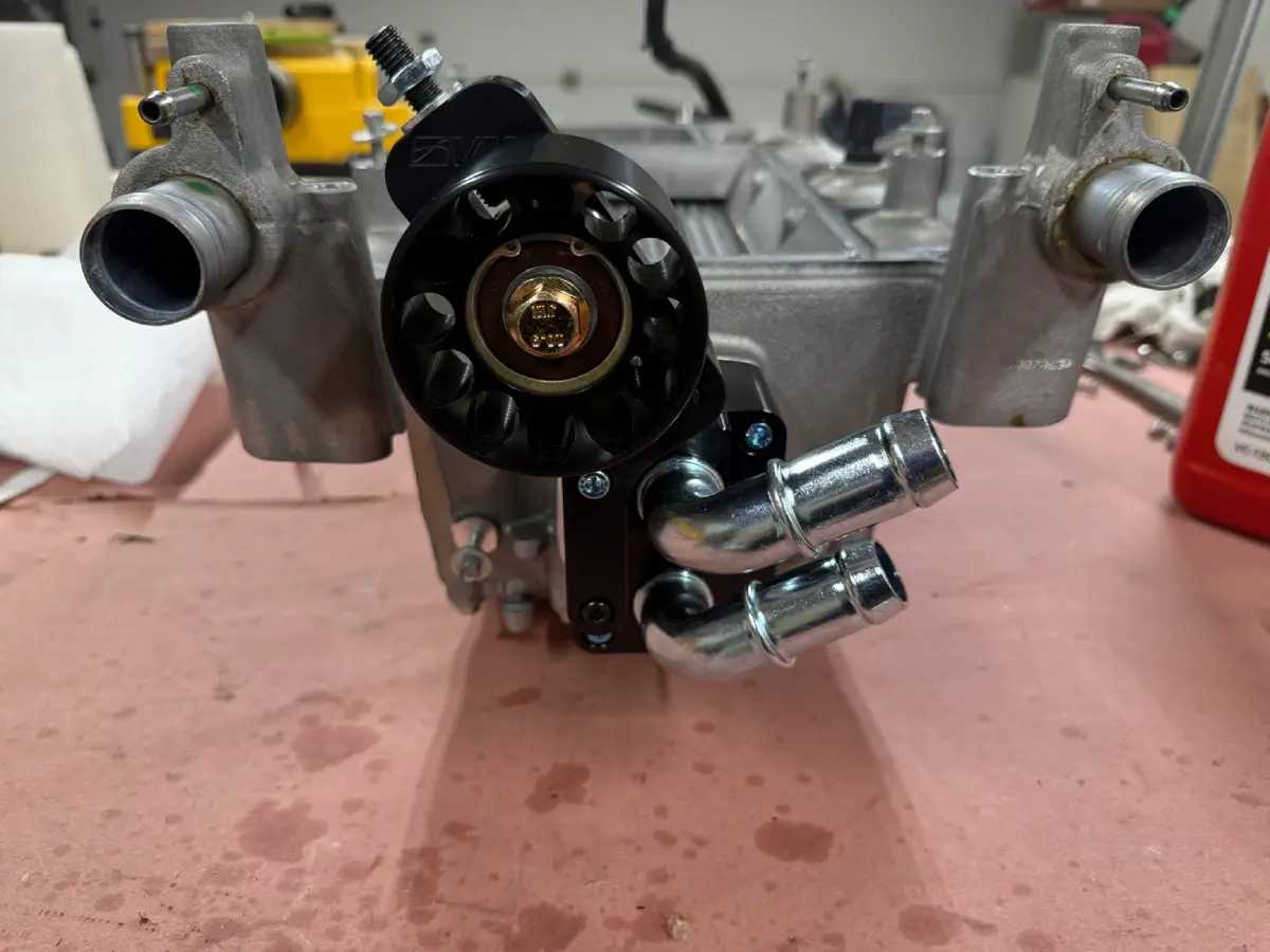
The detail I was less happy with was inside the manifold’s 90-degree hose connection tubes. On the part I received, the bends did not have a smooth, consistent internal shape. The passage narrowed through the inside of the bends, so it was not a uniform 1-inch opening along the entire path.
I considered that a remaining restriction in a component I had chosen to improve coolant flow. The larger connections were a step in the direction I wanted compared with stock, but I would have preferred a smoother, more consistent passage through the bends.
I did not flow-test the manifold, so I cannot put a number on the effect of that narrowing. This is an observation about the part I installed and an area I would inspect when evaluating the hardware.
Also, the “1-inch” description here refers to the manifold version and matching transfer tubes. Most of the external intercooler plumbing in my complete cooling build uses 1.25-inch hose. The sizes and transitions across the whole circuit matter when planning the system.
For reassembly, I used new intake manifold gaskets purchased from Tasca Ford and the VMP Boost-Lok supercharger gasket listed above. I continued using the service manual to reference the assembly procedure and torque specifications.
Filling the intercooler circuit took more patience than installing the main components. My hose routing had to accommodate the space planned for future radiator ducting, which made the coolant path more complicated than stock.
I spent a considerable amount of time burping the system and squeezing the hoses to help move trapped air out. On this build, filling and bleeding needed time of their own; they were a substantial part of finishing the job.
Before considering an installation complete, check the hose connections and manifold area for leaks, confirm coolant circulation, and recheck the level once the system has cooled. A filled reservoir alone does not establish that the entire circuit is free of trapped air. Follow the bleeding procedure appropriate to your pump and plumbing arrangement.
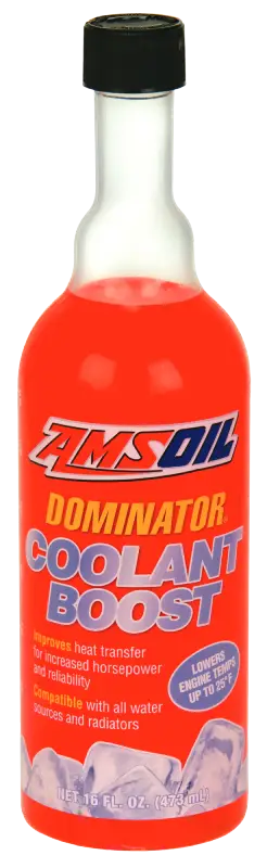
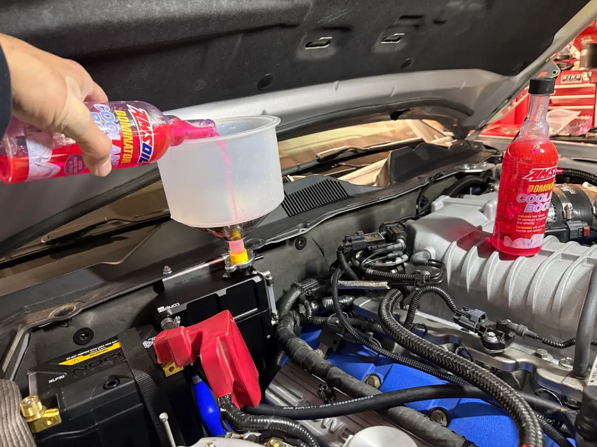
For this track setup, I used distilled water with AMSOIL DOMINATOR Coolant Boost in both cooling loops.
The supercharger removal and intercooler swap were manageable with basic hand tools, a torque wrench, and reference from the service manual. The extra tools that made the difference were the hose clamp plier for the rear coolant hose and the crowfoot wrench for the intercooler mounting bolts.
If I were preparing for this job again, I would focus on four things:
This GT500 intercooler upgrade was one part of a larger cooling project that also involved the heat exchanger, pump, hose routing, radiator arrangement, and airflow management. I do not have an isolated before-and-after test that assigns a temperature improvement to the VMP brick or manifold alone. Several components changed together, so the complete system needs to be evaluated as a whole.
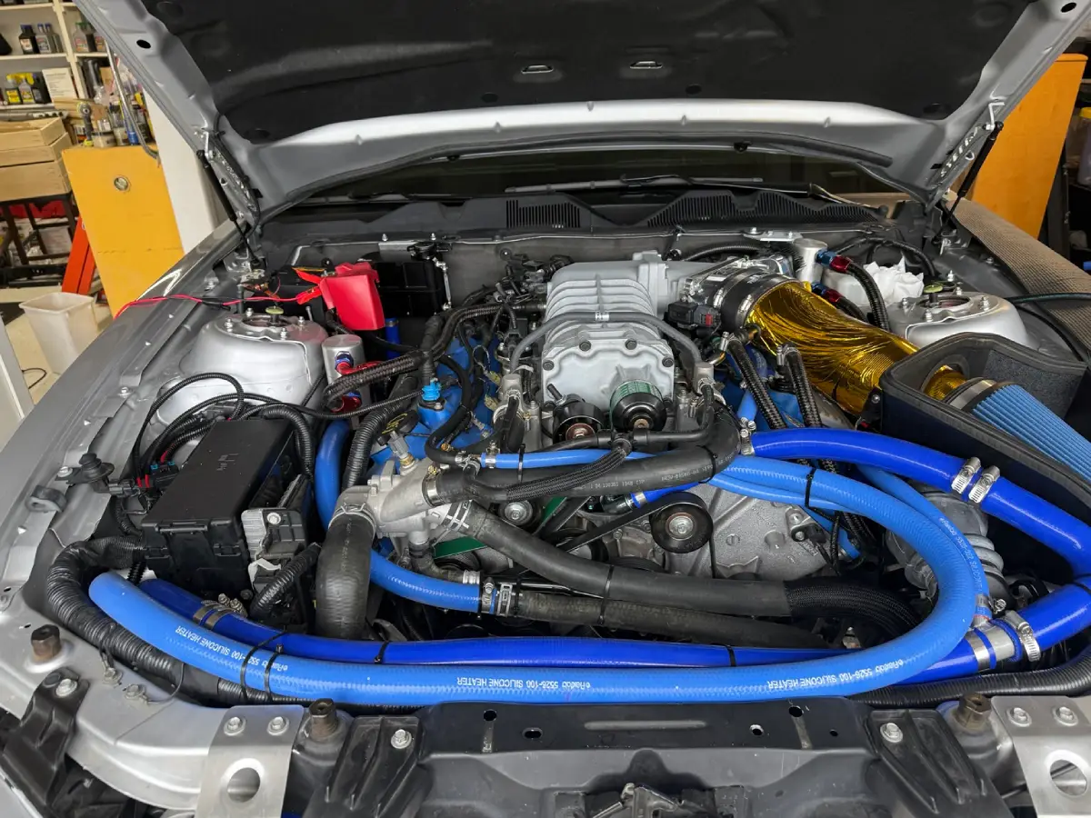
You can follow those changes in my 2012 Shelby GT500 track-car build.
If you are interested in the coolant additive I used, you can see AMSOIL DOMINATOR Coolant Boost here. I am an independent AMSOIL Dealer and earn a commission from qualifying purchases through my link.